The goal
Portable radios, batteries, and computers have become easy to pack and operate from a hotel room. The antenna is the remaining challenge. Portable wire antennas work well when you have space to stretch them out or something to hang them from, but those conditions rarely exist indoors.
The Hamdo began with three requirements: it had to be compact enough for a suitcase, self-supporting and practical to operate in a hotel room, and rugged enough to take a little abuse without breaking. The result is a resonant 20m antenna whose mast, tripod, whip, body, and counterpoise all collapse to less than a foot long.
Indoor operation is never ideal, but sometimes it is the only option available—and the antenna should not be the reason you cannot get on the air.
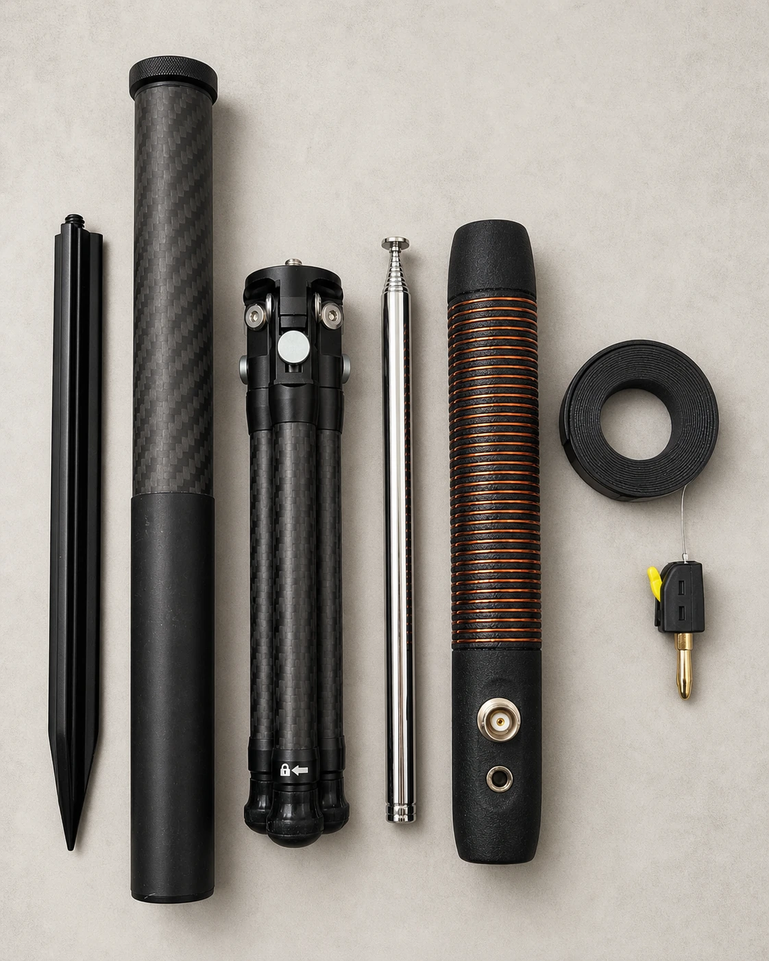
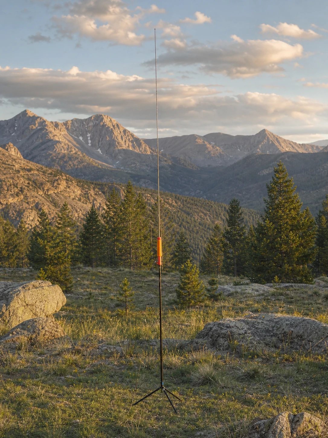
A compact tripod, one-meter carbon-fiber mast, telescopic whip, loaded Hamdo body, and reelable counterpoise. Each piece is sized for easy packing.
This is a compromise antenna optimized for portability. The loading coil is as small as I felt it could be while retaining useful efficiency. For maximum portable performance, I still reach for the POTA PERformer.
Parts list
The links below point to the exact items I used. Prices are what I typically saw while documenting the build and will change over time. Many items are sold in quantities large enough for several antennas.
Needle-nose pliers, razor knife, digital multimeter, soldering iron, solder, 3D printer, and filament.
My starting cost was about $190 in parts and specialized tools, excluding the general shop items above. The bulk-package sweet spot is roughly five builds.
Build the Hamdo
Read through the complete process before starting. The long 3mm T-handle hex key is essential: it lets you capture and tighten the upper coil screw from inside the body.
Print and prepare the body
- Print the body. I recommend PETG-CF; use at least PETG for the finished antenna.
- Press the 1/4-20 heat-set insert into the bottom of the Hamdo.
- Press the M4 heat-set insert into its recessed opening at the top.
- Temporarily thread an M4 × 18mm screw into the top insert, then remove it. This clears any debris left during installation.
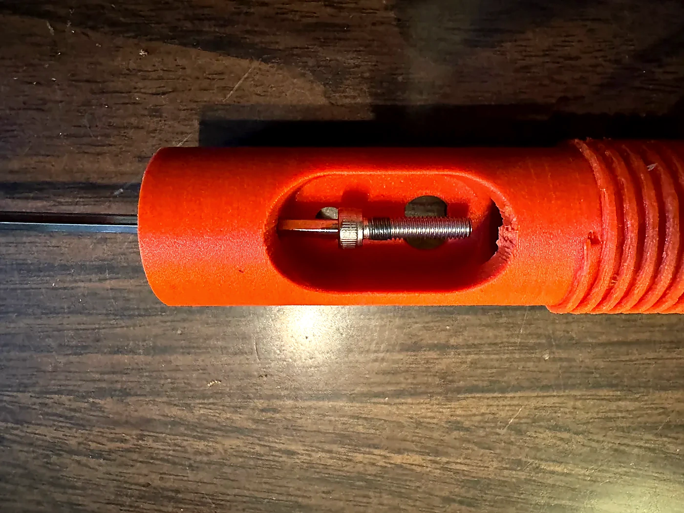
- Feed the long 3mm T-handle hex key through the 1/4-20 insert in the bottom until it reaches the large body opening.
- Place an M4 × 18mm screw on the hex key, guide it through the body to the top opening, and thread it into the insert. Do not fully tighten it yet.
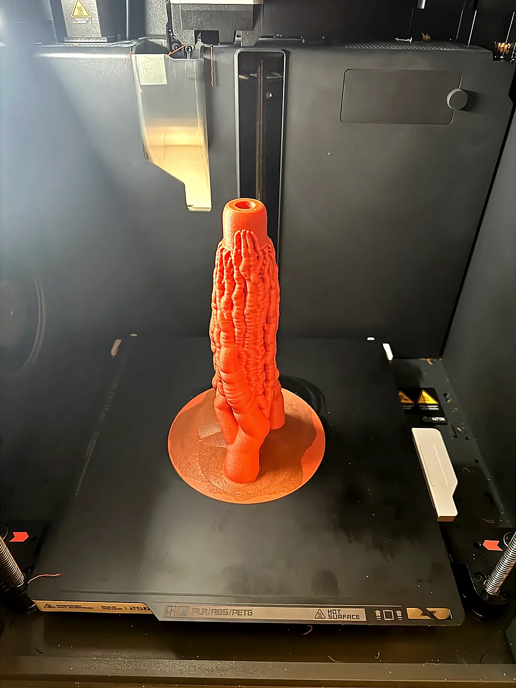
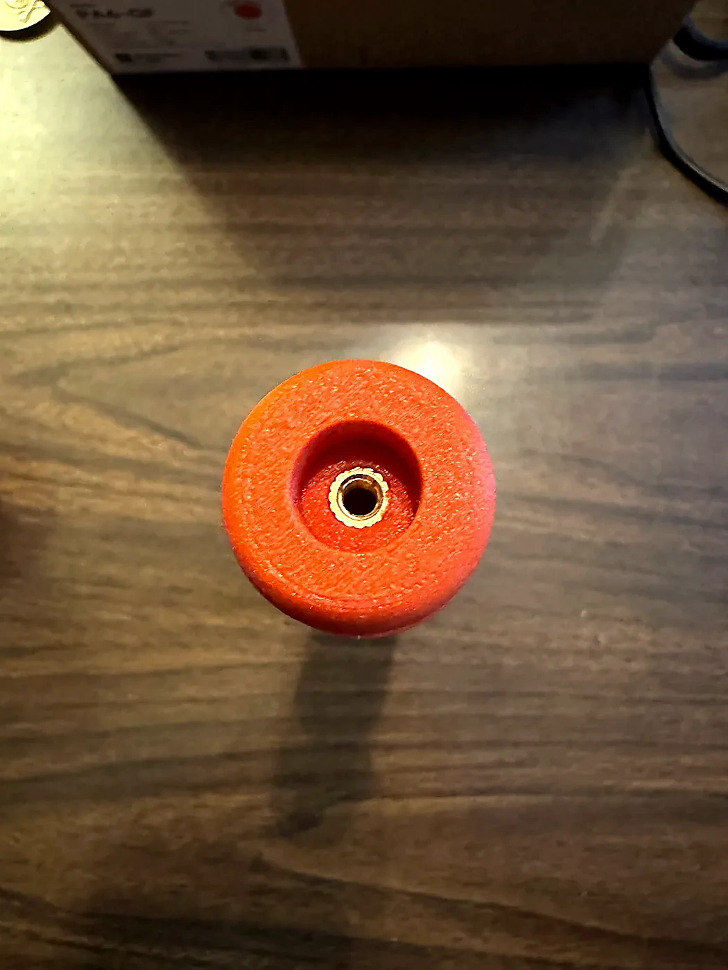
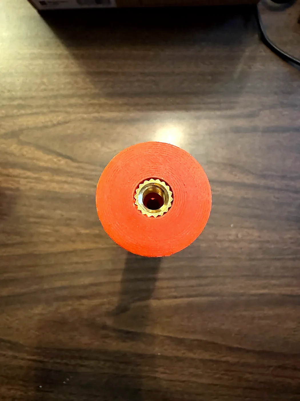
Wind the loading coil
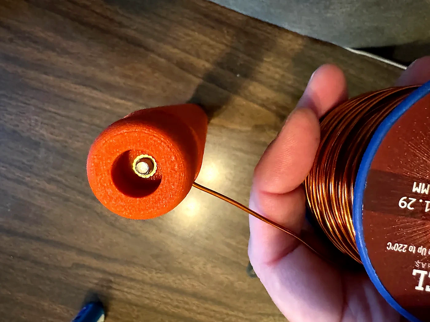
- Remove the enamel from roughly one inch of the 16 AWG magnet wire.
- Insert the stripped end into the hole at the top of the coil form.
- Use the long hex key to tighten the M4 screw and clamp the wire. Confirm that the screw physically captures it.
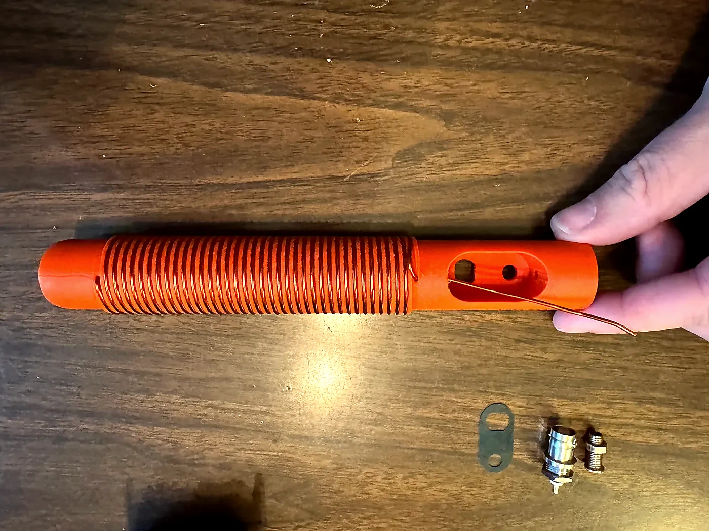
- Wind the wire around the coil form until you reach the lower hole. Keep each turn tight and seated in its channel.
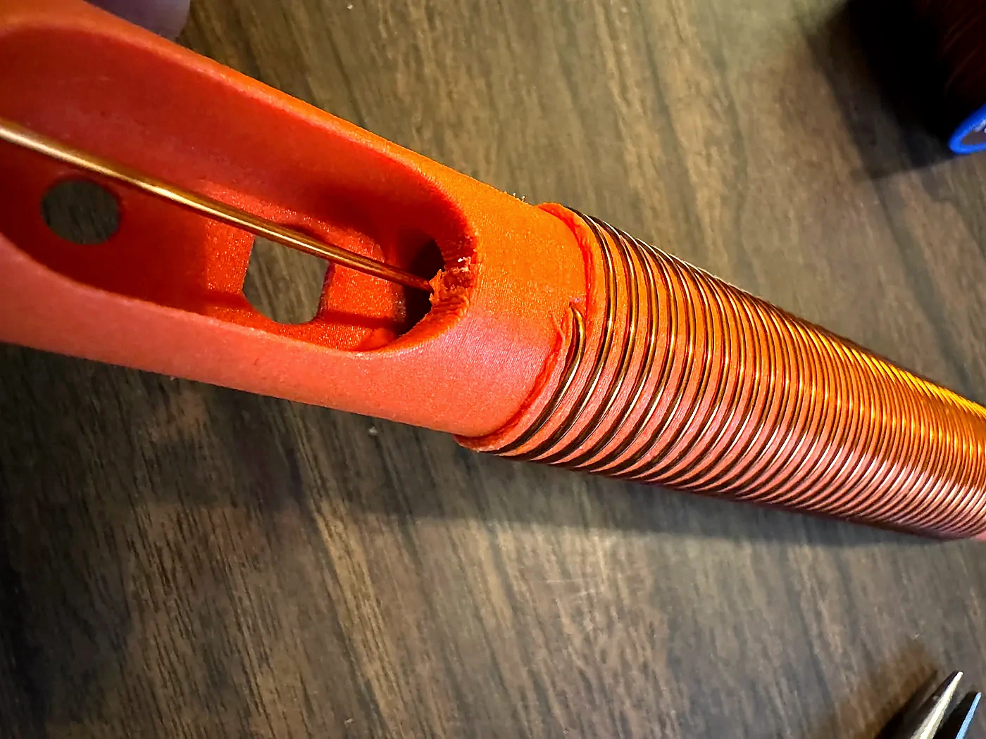
- Cut the wire with about four extra inches, then feed the end through the lower hole and into the body.
- Reach through the large opening with needle-nose pliers, grab the wire, and pull it out through the opening.
- Inspect the entire winding. Correct skipped guides, tighten loose turns, and pull the lead snug at the lower feed-through.
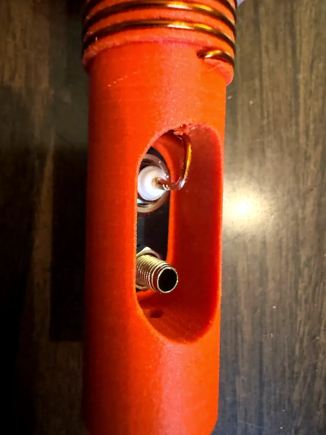
- Bend the lead out through the large opening so it is clear for connector installation.
Install the ground plate and connectors
- Remove the nut, solder tab, lock washer, and loose hardware from the panel-mount BNC connector.
- Test-fit the BNC connector in the ground plate. Expect a tight fit; it provides structural stability and electrical contact.
- Remove the solder tab and plastic components from the banana socket, then test-fit it in the ground plate as well.
- Remove both connectors and place the ground plate into the Hamdo's large opening.
- Install the BNC through the front of the Hamdo so its threads pass into the large opening and capture the ground plate.
- Set the Hamdo BNC-side down on a flat surface. Use a correctly sized socket as a press tool to firmly seat the ground plate against the back of the BNC. The plate should sit flat against the inside face of the body.
- Start the BNC nut, but do not tighten it yet.
- Install and fully seat the banana socket through the body and ground plate in the same way, then start its nut.
- Once everything is seated and aligned, snug both nuts to secure the assembly.
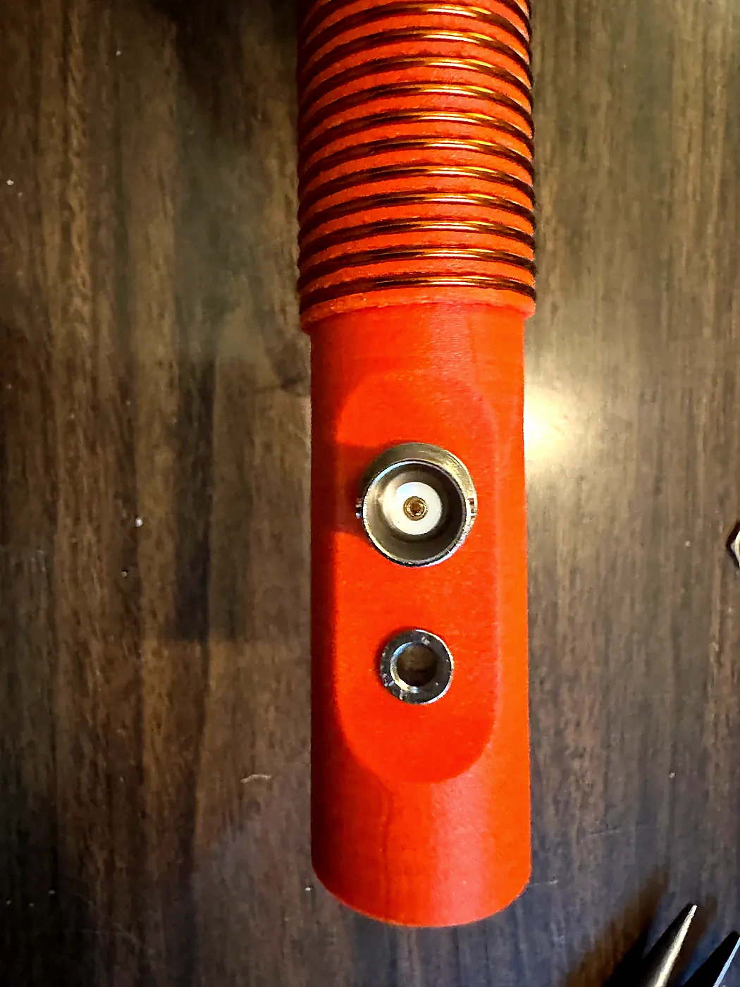
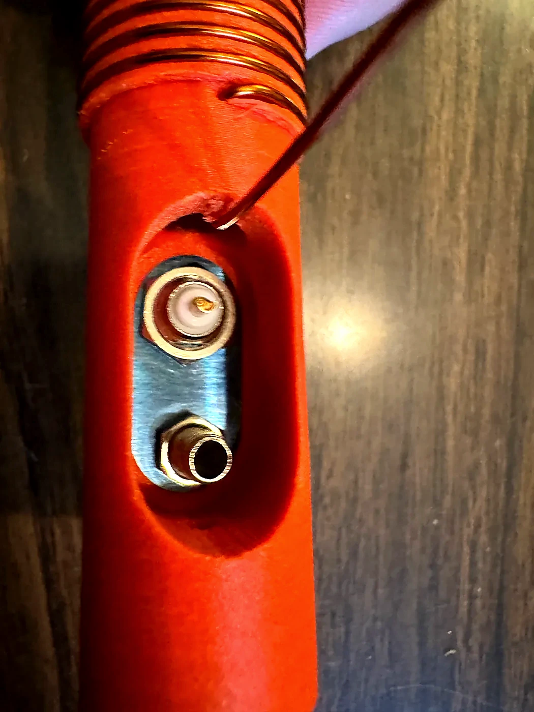
The negative ring solder tabs that come with the banana-plug socket and BNC connector can replace the custom ground plate. Use the Hamdo body to establish the correct spacing, remove the hardware, solder the two rings together outside the body to create the electrical ground connection, allow the assembly to cool, and then reinstall it. Do not solder the rings together inside the Hamdo—the sustained heat can damage the printed body. This approach works and eliminates custom plate fabrication, but it is not structurally ideal: without the plate, the connector mounting face has less reinforcement and is more vulnerable to flexing or damage.
You can deform the printed body or break a connector. I have broken several banana sockets this way. The hardware should be firmly installed—not crushed into place.
Solder and test
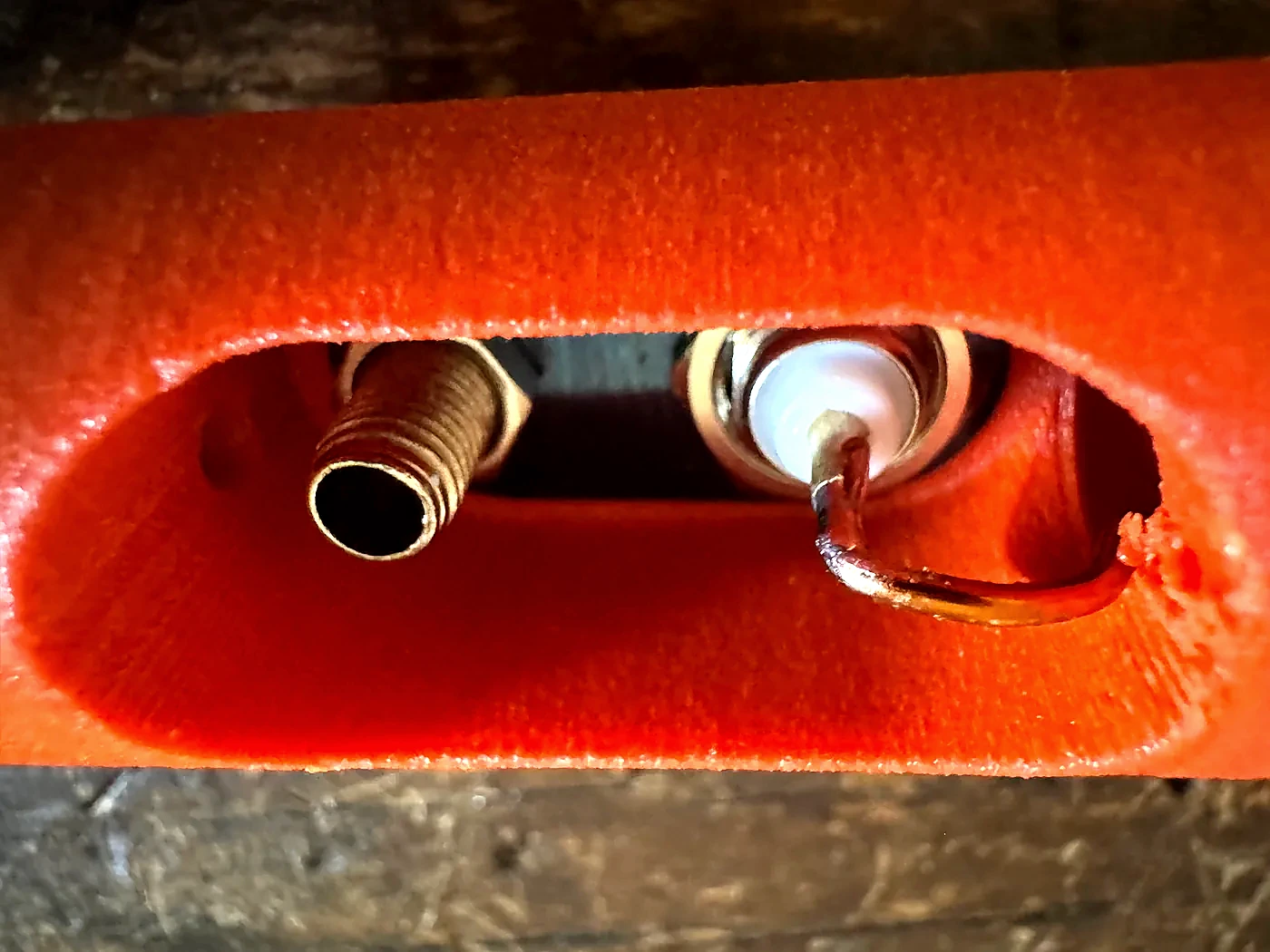
- Shape the coil lead to reach the BNC center-pin solder cup. I run it straight down, then make a 90-degree bend into the terminal.
- Fit, measure, and trim the wire. Bend it back out, then thoroughly scrape the enamel from the section to be soldered.
- Return the lead to its final position and solder it to the BNC center pin.
- Keep the iron off the printed body. Work deliberately with a hot iron and add flux if available so the joint forms quickly.
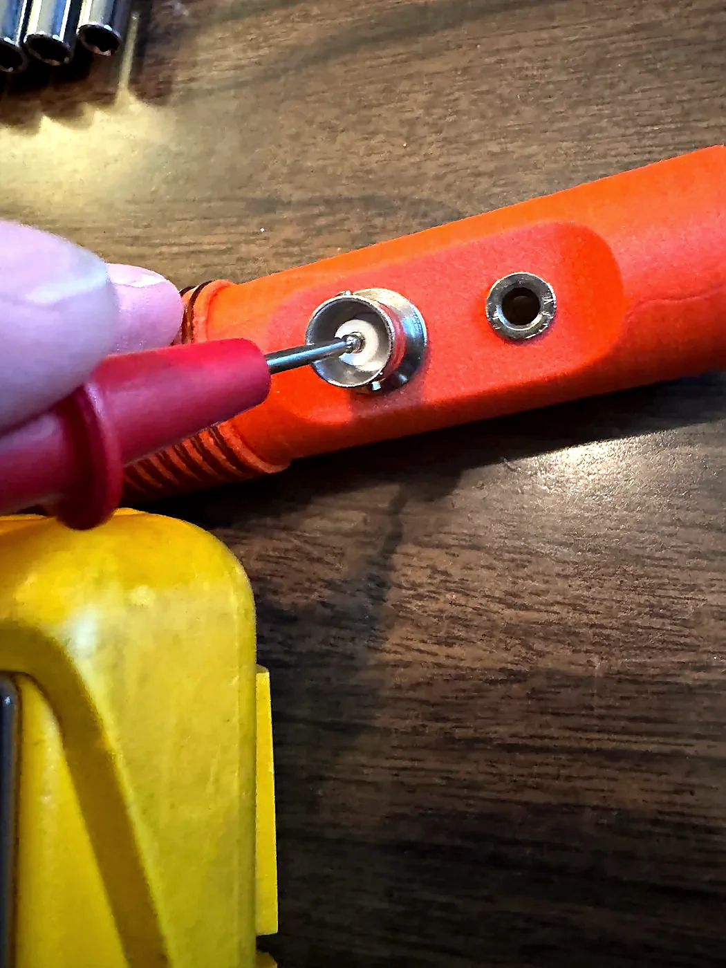
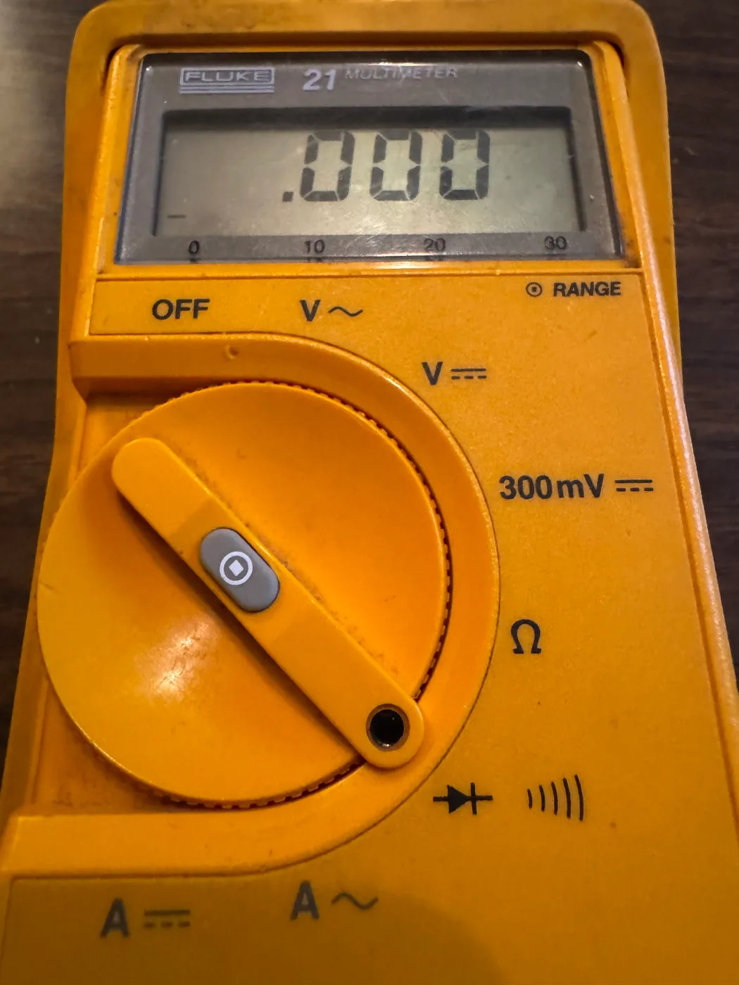
- Use a digital multimeter to check continuity from the BNC center pin to the M4 screw at the top of the Hamdo. It should read essentially zero resistance.
- If continuity fails, inspect the BNC solder joint, both scraped sections of magnet wire, and the upper screw clamp.
Make the counterpoise
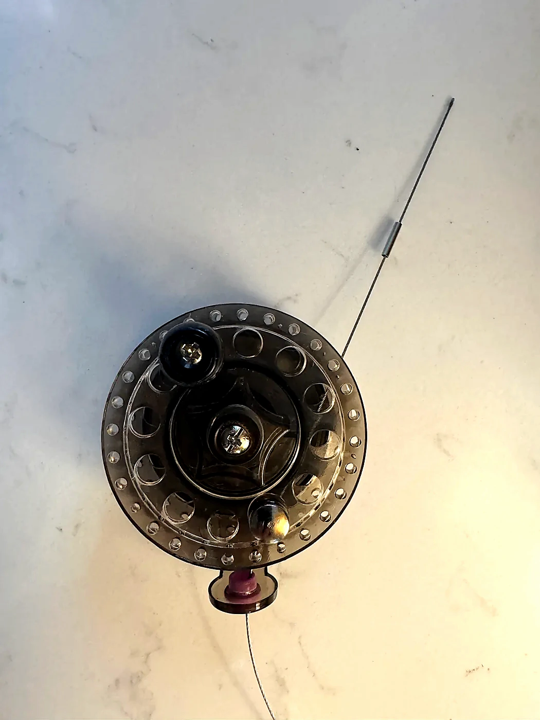
The reel lets you deploy only the electrical length you need. I use this same counterpoise with the Hamdo and POTA PERformer, and the full wire can serve as an end-fed half-wave antenna.
- Feed the stainless-steel wire rope through the eye of the reel.
- Slide the smallest single-barrel sleeve from the Booms kit onto the wire, inside the reel eye.
- Loop the wire through two holes in the side of the reel, then feed the loose end back through the sleeve.
- Pull the loop to the desired tightness and crimp it with the CP2 tool.
- Measure at least 17 feet of wire from the reel. I prefer 34 feet so the wire can also be used as an EFHW antenna.
- If you want crimp-on measurement markers, thread the beads onto the wire now.
- Use another sleeve to form and crimp a loop about 1/2 inch long at the free end.
- Flatten the loop, insert it into the quick-connect banana plug, and clip the plug closed.
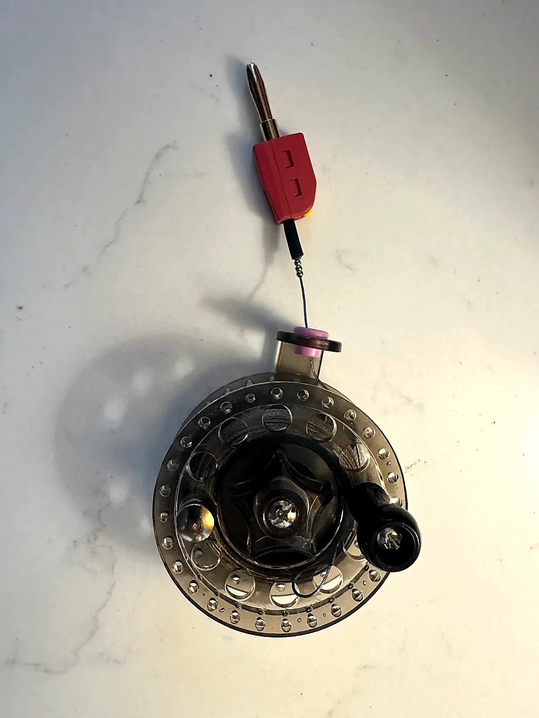
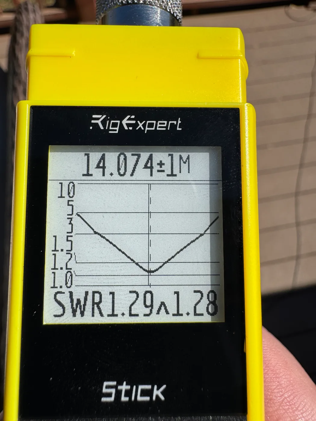
Use a NanoVNA to find the Hamdo's tuned ground-radial length, then add a marker at the 20m quarter-wave point. You can add others for repeat locations; even an indoor radial may need its own length because nearby structure and ground coupling change the tune.
Set up and operate
- Screw the mast into the tripod.
- Screw the Hamdo into the mast.
- Screw the telescopic whip into the Hamdo.
- Extend the tripod legs and adjust them until the feet sit completely flat.
- Extend the mast, then fully extend the whip.
- Connect the counterpoise and unreel the appropriate starting length for a ground or elevated radial.
- Connect the ferrite end of the coax to the Hamdo's BNC connector.
- Use an antenna analyzer to tune the radial length. I use an inexpensive NanoVNA.
On-air testing
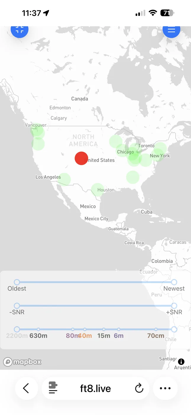
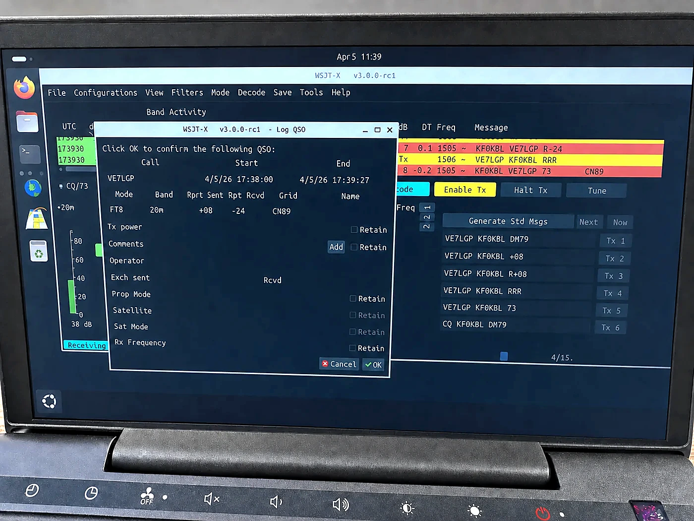
An analyzer confirms resonance, but an on-air test shows whether the complete system is actually radiating. For this test, I transmitted FT8 at 100 watts with the counterpoise elevated and deployed to one-quarter wavelength. The ft8.live reports show where the Hamdo's signal was decoded, and I completed a 20m contact with VE7LGP in grid CN89.
100 watts
Elevated, one-quarter wavelength
Performance & power
Field tested
I have run a PA6-GF Hamdo at 100 watts for hours during a POTA activation with no ill effects. A second PETG-CF build produced the same result.
Purpose-built
The Hamdo is a single-band resonant antenna. Its short loaded form trades some efficiency for the ability to pack and deploy almost anywhere.
I printed a PLA body but never completed or operated that antenna. Its power handling and long-term performance are unknown, so PETG or a more heat-resistant material is the safer choice.
Acknowledgements
The Hamdo is my own implementation, but it did not emerge in isolation. These operators and designs helped inspire and shape the project.
Ham Radio Duo
The Just OK Antenna helped shape the Hamdo’s compact, loaded-whip direction and reinforced the goal of building an antenna that is easy to pack and practical to deploy.
Greg Mihran (KJ6ER)
The POTA PERformer influenced the Hamdo’s portable, elevated, resonant architecture and its use of a tuned radial or counterpoise as part of the complete antenna system.
Read the POTA PERformer plans ↗Simon “HamJazz” Stribling
Simon’s use of a reel to vary antenna or radial length inspired the Hamdo’s reelable counterpoise, which can be deployed to the electrical length needed for a given setup.
Visit HamJazz on YouTube ↗License
Community use with attribution
The Hamdo antenna design, Hamdo_v.63.stl, GroundPlate.dxf, and the KF0KBL-authored build documentation on this page are distributed under the Open Community License v1.1 with General Attribution v1. Third-party products, linked resources, and the acknowledged designs that inspired the Hamdo are not included in this license grant.
May use, copy, modify, and build the Hamdo for noncommercial purposes.
Must remain under OCL v1.1 + GAtt v1 and identify KF0KBL as the original creator.
May use the design internally, but commercial replication or sale requires a separate license.
This summary is provided for convenience and does not replace the license. The complete OCL v1.1 and GAtt v1 texts govern. The license applies only to intellectual property rights held by KF0KBL.